| Part No. | Power Source | Energy [Kw/h per pulse] | Volume [m3 per pulse] |
|---|---|---|---|
| DHM PIPO-1L | Battery 3v Li | 1 | 0.1 |
| DHM PIPO-10L | Battery 3v Li | 10 | 0.1 |
| DHM PIPO-100L | Battery 3v Li | 100 | 1 |
| DHM PIPO-1000L | Battery 3v Li | 100 | 1 |
| DHM PIPO230VAC-1L | 230v AV 50Hz | 1 | 0.1 |
| DHM PIPO230VAC-10L | 230v AV 50Hz | 10 | 0.1 |
| DHM PIPO230VAC-100L | 230v AV 50Hz | 100 | 0.1 |
| DHM PIPO230VAC-1000L | 230v AV 50Hz | 100 | 1 |
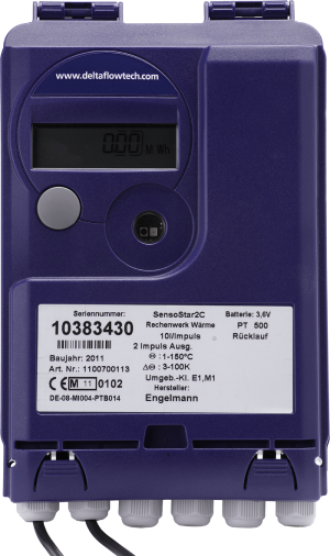
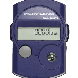
Wall Mounted Calculator
- MID Approved
- BMS output
- Pulsed output [Kw/hr], M-bus or 4-20mA versions
- Dn 15-300 applications
- Battery or 230v AC versions
- IP65 protection rating
- EMC Class C according to EN1434
- Measurement range: 1 – 150°C
- Ambient temperature: 5 – 55°C
- Temperature resolution: 0.01°C
- Measuring frequency: 20 – 120 seconds
- No data loss when battery removed
- PT500 sensors
- For use with Mechanical, Ultrasonic or Magflow meters
- Two pulsed inputs available as standard
Additional Features
- Continuous display of the accumulated heat energy on a large LCD display
- Application-oriented display menu; easy to scan using operating key
- Data storage six times a day in non-volatile memory
- Hourly self-check
- 12 monthly values readable on the display or via the optional interface
- Available lengths of temperature sensors: 3m [2-wire type] and 10m [4-wire type]
- Installation in temperature pockets of various lengths possible.
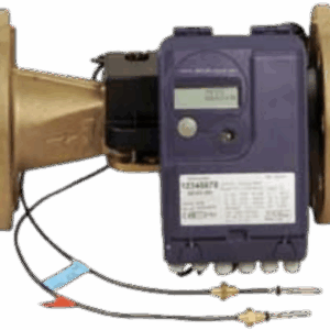
Description
- Affix the wall mounting bracket [supplied with the calculator] to the wall and clip on the calculator.
- Connect the wires as described below [for the pulsed BMS output].
- Clip the calculator on the output module
- Remove the terminal cover on the front of the calculator.
- Connect two wires from water meter to left hand terminal [NOT polarity sensitive] to give pulsed input flow rate.
- Re-fit terminal cover.
- Connection of the pulse output unit
- To clamp on the pulse output for energy: the clamps 7 and 8 must be connected.
- The short circuit wire between 4 and 5 must be removed.
- To clamp on the pulse output for volume: the clamps 3 and 4 must be connected.
- The short circuit wire between 8 and 9 must be removed.